Road Area Coding
|
Navigation Links |
Introduction
The following content discusses the topic of Road Area Coding. This information provides a model and a method with reference to variables concerning the Road Area. Real-world examples are illustrating the method by showing pictures from the accident scene and how these cases are coded. Please read the section “Definitions” for specific vocabularies providing better understanding of the content.
A different way of coding the road geometry
This is one option to standardize the data/information about the Road Area collected from the accident scene. This standardized method simplifies the way of inserting the data and the interpretations of the road geometry coded. In particular, this method simplifies the interpretations of the coded information for persons not involved in collecting accident data.
Definitions
DB (Database) Road Direction
Is marked in the sketch where the vehicles were situated at the start point of the accident scenario and defines the coded road section. Should be defined for all roads added to the database (A, B etc.) where vehicles involved in the accident have been travelling (see example 2). If two or more vehicles travelling on the same road, the DB road direction should be defined by Vehicle 1 travelled direction.
Design Order
The order of the added road component types at the road area section. In the database this number is automatically generated but can be changed by drag and drop.
Road Area
Is the total area containing both the road way (paved area, including lanes and shoulders) and the road-sides (both the side of the road and the median area if any).
Median with Barrier
A roadway where the traffic is physically divided with a median and a road restraint system (barrier).
Method
This section provides the method concerning Road Area coding. Please see the following steps below;
- The road area should be coded at the first point of impact if it is a collision on a single road. For run off road accidents the road area should be coded at the point where the first wheel leaves the road area. For accidents in intersections/crossroads each road should be coded before the intersection starts.
- Select a photograph in which you can draw a line which corresponds to where the road area should be coded (i.e. where the road measurements are taken).
- Define and trace the “DB road direction” on the Road Area picture and on the road sketch for all vehicles directions involved in the crash. If two or more vehicles travelling on the same road, the DB road direction should be defined by Vehicle 1 traveled direction.
- The design order should start at the leftmost component type of the Road Area. This component will be denoted design order 1.
- All components of the paved road area (road way) should be coded including hard shoulders, lanes and markings etc. Inactive lanes on the other side of a centre line might not have been measured and will be coded inactive. If the road area includes a median an exception can be made (see section”Exceptions” below). If the roadside(s) have been inactive (no vehicles have left the roadway i.e. paved area) it does not have to be coded.
Example 1
An accident occurred on a road area with four lanes (two in each direction) and the driving direction is separated with a single solid line, see Figure 1.1. No vehicle was entering the roadside therefore it is inactive and not coded.
Table 3.1, shows the coded information from the road area.
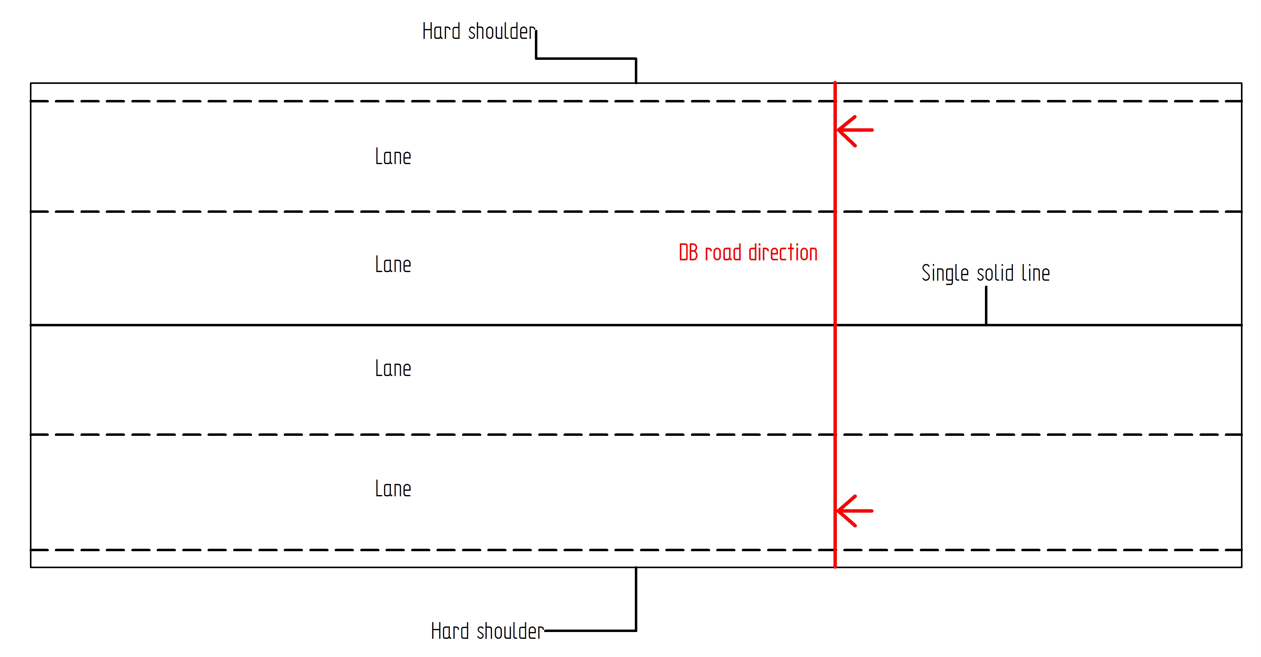
Figure 1.1 Road with 4 lanes.
Table 3.1 Design order of the coded road area.
| Design order | Road type | Road component sub type |
|---|---|---|
| 1 | hard shoulder | N/A |
| 2 | marking | single dashed line |
| 3 | lane inactive | N/A |
| 4 | marking | single dashed line |
| 5 | lane inactive | N/A |
| 6 | marking | single solid line |
| 7 | lane inactive | N/A |
| 8 | marking | single dashed line |
| 9 | lane active | ahead |
| 10 | marking | single dashed line |
| 11 | hard shoulder | N/A |
Exception
Adding information about a motorway could imply a big amount of road components. Therefore an exception should be used to simplify the implementation. If the motorway contains a “median with barrier” the opportunity arises to set this component type to design order 1. By using this operation the total amount of elements at the road section will be reduced while the correct amount of data to understand the important information of the road area still prevails.
This coding exception should be used if the road area acquires these criteria:
- The road is a motorway.
- The motorway contains a median with barrier.
- The other side of the median is totally inactive, inactive = did not contribute to or effect the start or outcome of the accident.
Accident Examples - Road Area Coding
Example 2
In Figure 5.1 an accident on a rural road with single carriageways (one lane in each direction) is shown, see Table 5.1 for the coding of the road area.
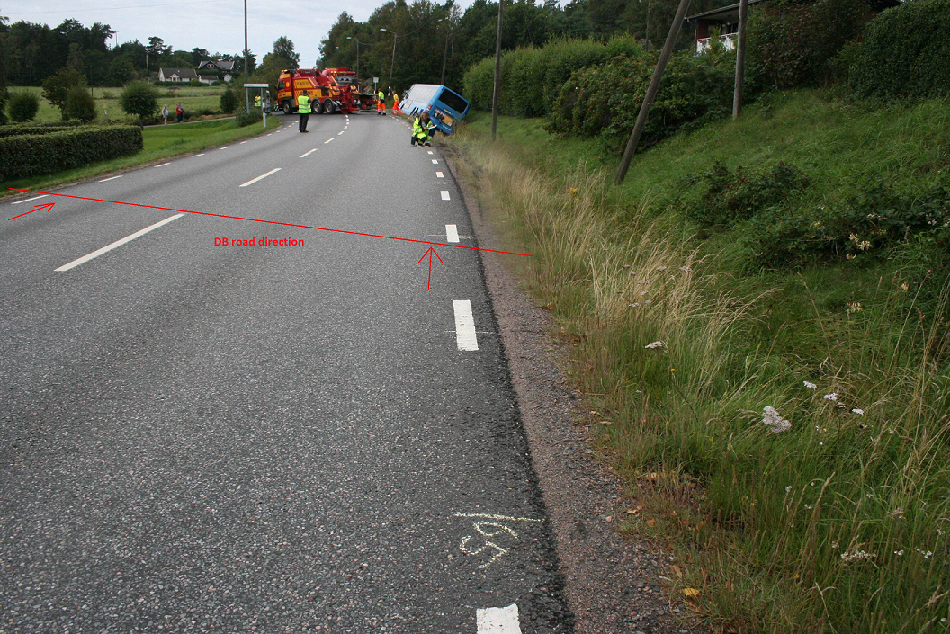
Figure 5.1 Defined DB road direction.
Table 5.1 Design order of the coded road area.
| Road number | Design order | Road type | Road component sub type |
|---|---|---|---|
| 1 | road a | hard shoulder | N/A |
| 2 | road a | marking | single dashed line |
| 3 | road a | lane inactive | N/A |
| 4 | road a | marking | single dashed line |
| 5 | road a | lane active | ahead |
| 6 | road a | marking | single dashed line |
| 7 | road a | hard shoulder | N/A |
| 8 | road a | road side active | N/A |
If an analyst or investigator not familiar with the road interprets the information in Table 5.1 the outcome is illustrated in Figure 5.2

Figure 5.2 Interpretation of the road area.
Example 3
In Figure 5.3 an accident on a city street with single carriageways (one lane in each direction) is shown, see Table 5.2 for the coding of the road area.
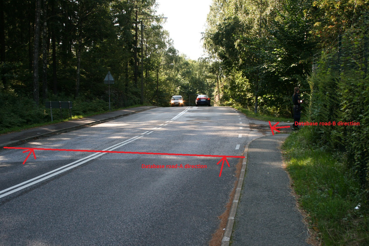
Figure 5.3 Defined DB road directions.
Table 5.2 Design order of the coded road area.
| Road number | Design order | Road type | Road component sub type |
|---|---|---|---|
| 1 | road a | hard shoulder | N/A |
| 2 | road a | lane inactive | N/A |
| 3 | road a | marking | double dashed line |
| 4 | road a | lane active | ahead + right turn |
| 5 | road a | marking | single dashed line |
| 6 | road a | hard shoulder | N/A |
| 7 | road a | hard shoulder | N/A |
| 1 | road b | lane active | all directions |
If an analyst or investigator not familiar with the road interprets the information in Table 5.2 the outcome is illustrated in Figure 5.4
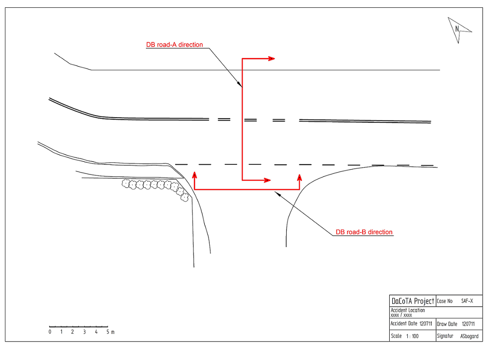
Figure 5.4 Interpretation of the road area.