Scene and Road Sketch
|
Navigation Links |
Purpose / Aim
The purpose of completing a scene and road sketch is to show all the relevant elements necessary for an accident reconstruction in one place. The sketch should include all relevant elements to enable a detailed accident reconstruction.
The sketch should be based on photos and measurements of the scene itself. It is recommended to take initial pictures of the accident scene, before creating chalk measurement markings. A second set of pictures can then be taken after the markings have been made. The markings should include a numbering of the evidence so that accurate correlations can be made between the pictures and the measurements.
A detailed scene and road sketch should include the following:
- The road and its surroundings, including infrastructure type (e.g. intersection, straight section, etc.)
- Relevant measurements (e.g. road width, road gradients, shoulder width, distances to roadside furniture, etc.)
- Road pavement markings (double line, turning arrows, etc.)
- Point of collision and final accident vehicle positioning
- Highlighted areas where accident evidence traces were found
- Accident vehicle brake and skid marks
- Road furniture, both fixed and mobile (traffic lights, signs, barriers, etc.)
- The initial driving direction of the accident vehicles
- Accident vehicle path(s)
- Position of collision objects before and after impact
- Pictures may also be included directly within the sketch
- Mark relevant roads with a ”DB Road Direction” marker, in case of multiple roads they should be coded with ”DB Road A Direction” , “DB Road B Direction” et.c.
- Ditch profile should be included if any vehicle has run off the road in to the relevant ditch. If so, the ditch profile can be included in the sketch as a cross section and as altitude lines along the roadway.
An example scene and road sketch is shown in the figure below.
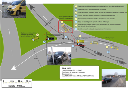
Figure 1: Scene and road sketch
Methods
The methodology for creating a scene and road sketch is divided into the following three steps:
- Perform the accident scene measurements.
- Create the initial draft sketch.
- Digitalise the initial sketch to a digital scaled sketch.
The methods outlined within this section should be applied in conjunction with relevant Detailed Methodology sections.
1. Accident Scene Measurements
The Accident Scene Measurements methodology is detailed in the Scene Measurements section.
2. Initial Sketch
By following the Scene Measurements methodology, accident investigators should be able to create an initial hand drawn sketch of the accident scene, including all relevant points of interest.
An example initial sketch is shown in the figure below.
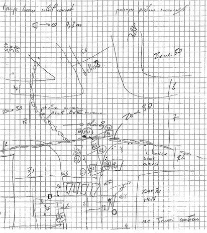
'''Figure 2: Initial hand drawn sketch
3. Digital Scaled Sketch
As the initial sketch may be difficult for others to understand, it is important digitalise the initial draft. Furthermore, a digital sketch can also be properly scaled. The final scaled sketch can better enable the accident reconstruction process.
An example scaled sketch (based on the above example initial sketch) is shown in the figure below.
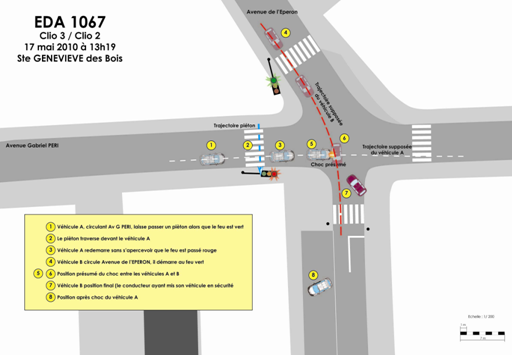
Figure 3: Scaled digital sketch
There are a number of different software packages available to facilitate the creation of a digital scaled sketch (i.e. Adobe Illustrator, PC Crash, PC Rect, etc.). A suitable software program should be selected to allow for a clear and accurate plan to be made.
For further information on PC Crash and PC Rect, please see here.
Equipment
Please refer to the Equipment List for the Scene and Road Plan equipment list.
Arrangements
Please refer to the Arrangements section of the Methodology Outline Scene and Road section.